Programming with EM
Turning now to the EM runtime, a series of curated "guided tours" will incrementally introduce components of the em.core bundle – many of which you may have browsed in your reading of Introducing EM. By convention, each tour revolves around a specific EM program found in the em.examples.basic package – with each of these small programming examples motivating us to visit key elements of the EM runtime.
In the material that follows, we'll reference a number of logical MCU "pins" configured by the current EM distro and generally accessible through headers on your target board:
appBut |
application button pin |
appLed |
application LED pin (usually green) |
appOut |
application console TX pin |
sysDbgA |
system debug pin A |
sysDbgB |
system debug pin B |
sysDbgC |
system debug pin C |
sysDbgD |
system debug pin D |
sysLed |
system LED pin (usually red) |
A special YAML file named em-boards found the em$distro package folder binds these logical pin names to physical pin numbers of your target board. Porting EM will have more to say about em-boards, as well as explain the special setup-*.properties files located in the root of your distro bundle.
Tour 00 – guided tours
The following animation illustrates the EM - Start Tour command, which you'll use to view each of the tours described in the remainder of this document. You'll find these tours in appropriately named .emtour files, located inside the .tours/101_Using_EM folder delivered with the em.docs bundle.

With that, go ahead and actually take tour 00_HelloP.emtour within your VS Code environment. Before proceeding to take Tour 01 – Tour 12 , however, you should feel comfortable with the UI presented in Tour 00 ; and do retake any of these tours whenever necessary.
Tour 01 – basic blinker
This tour centers around the BlinkerP program, which toggles the appLed pin on your target board – typically connected to a green LED. This tour also visits the BusyWaitI and LedI interfaces, as well as presents the Common module and its constituent proxies.
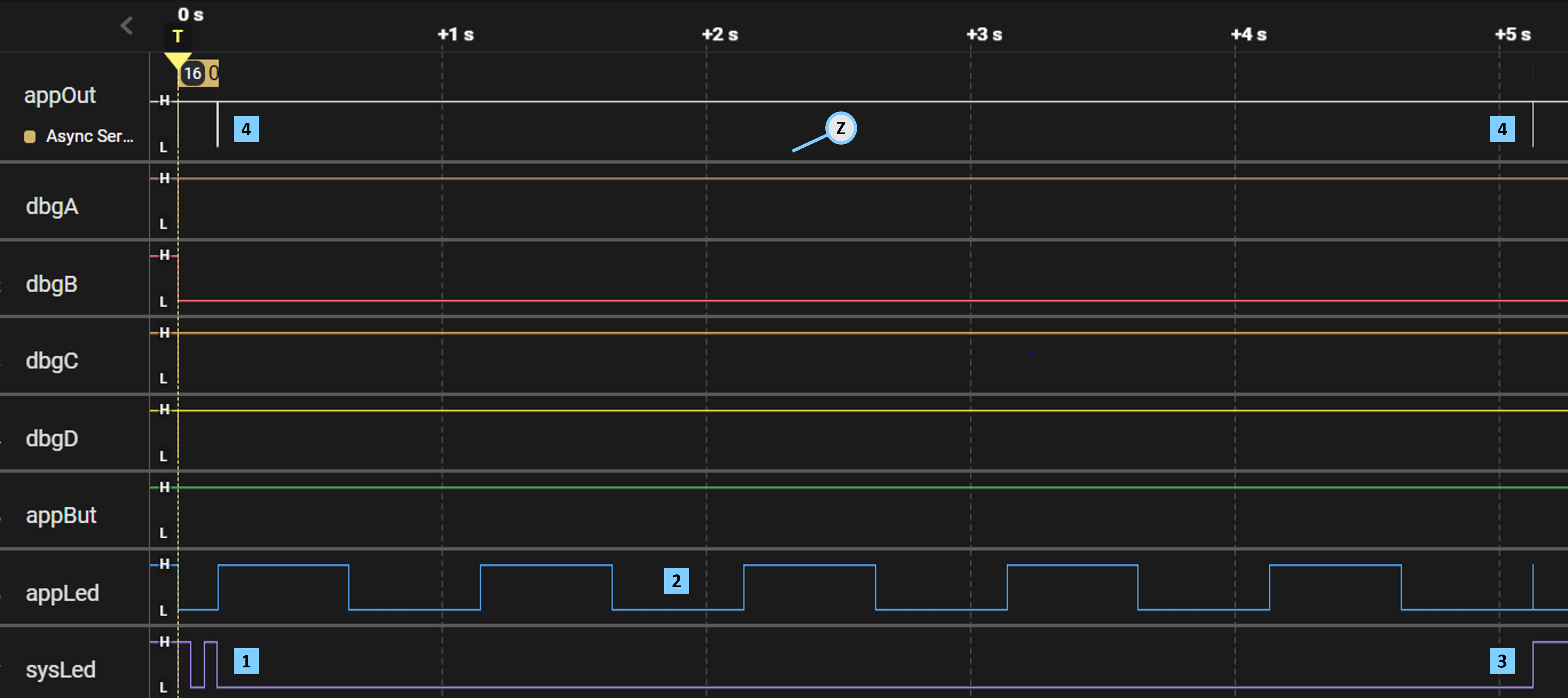
The EM runtime quickly blinks your board's sysLed at startup.
The BlinkerP program toggles appLed every ~0.5 s.
The EM runtime turns on sysLed upon normal program termination.
The next capture zooms into the appOut signal.

The EM runtime outputs this sequence of (non-printable) bytes at startup, after blinking sysLed.
The EM runtime output this single byte upon normal program termination, before turning on sysLed.
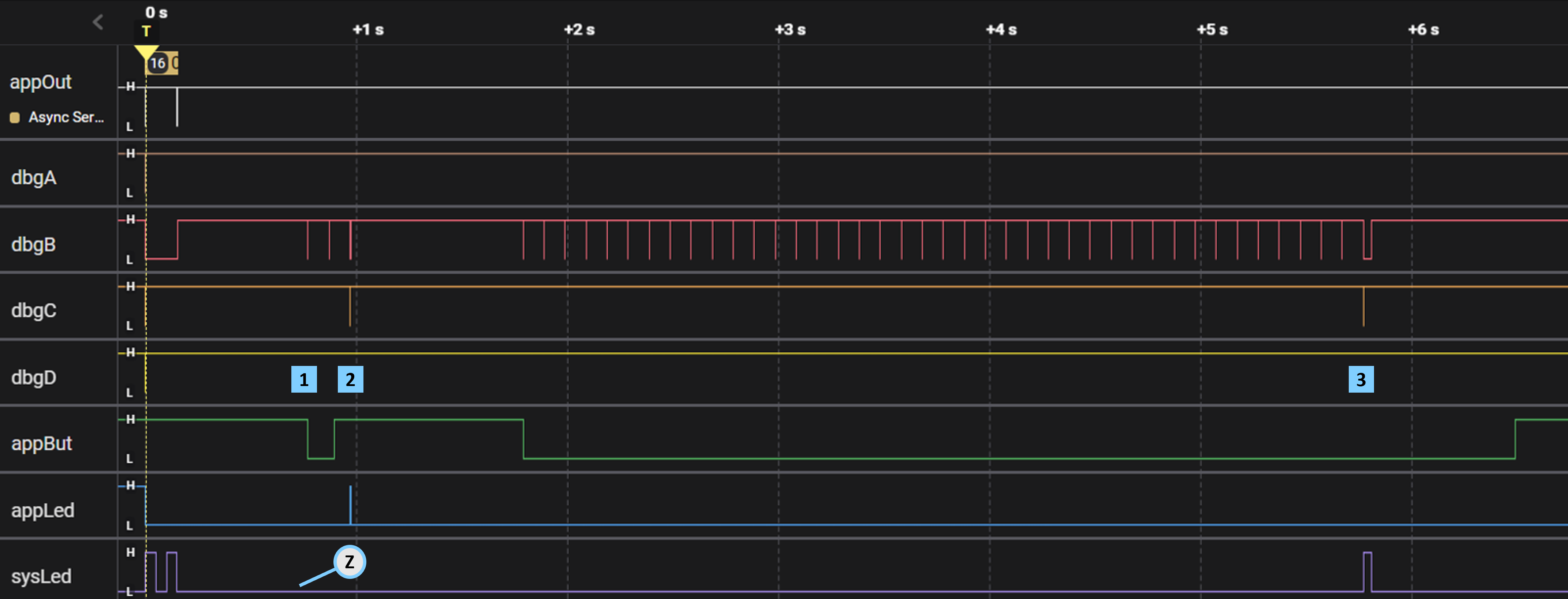
Tour 02 – real-time debug
This tour focuses upon the BlinkerDbgP program, which also toggles the appLed pin on your target board. This tour highlights a number of capabilities within EM for visualizing and troubleshooting program execution in real-time.
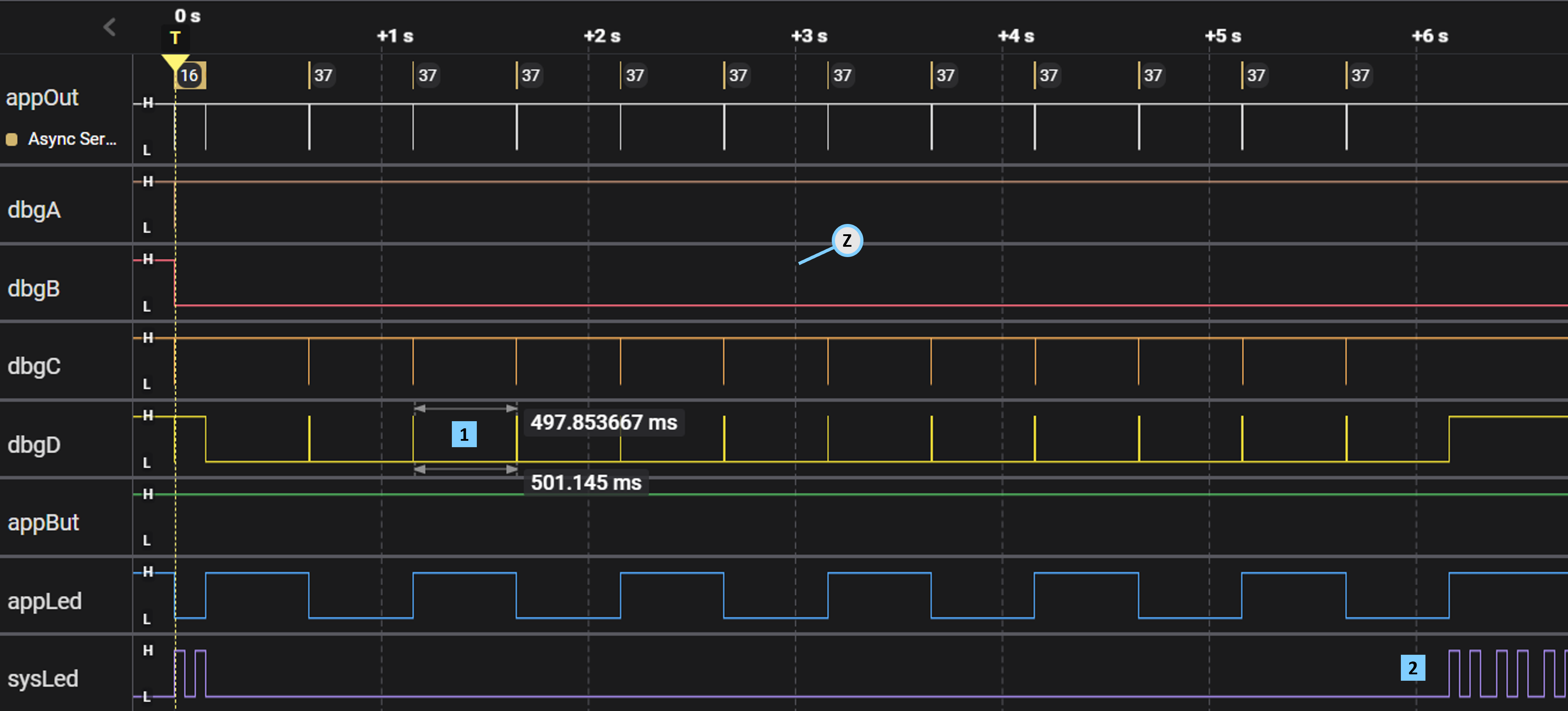
The busy-wait bracketed by %%[d+] and %%[d-] measures ~498 ms.
Executing a fail statement causes sysLed to blink rapidly.
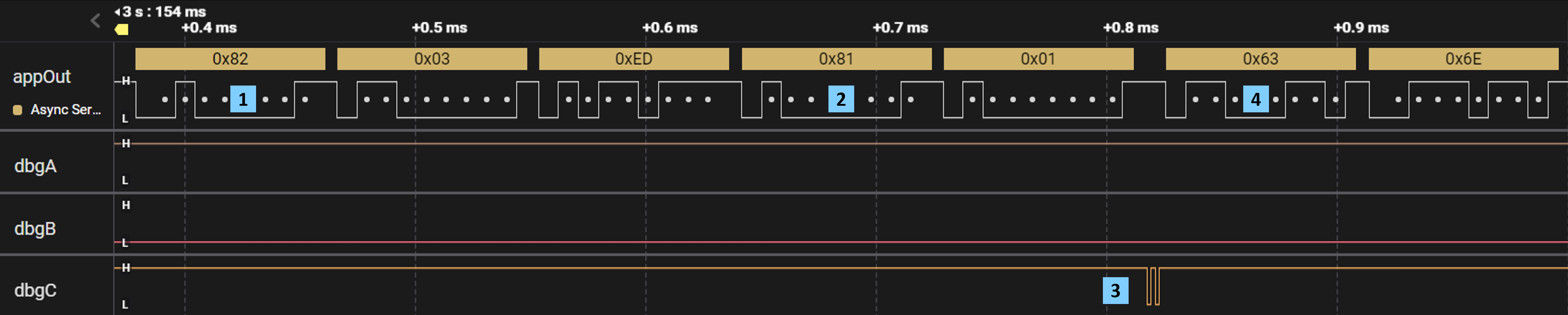
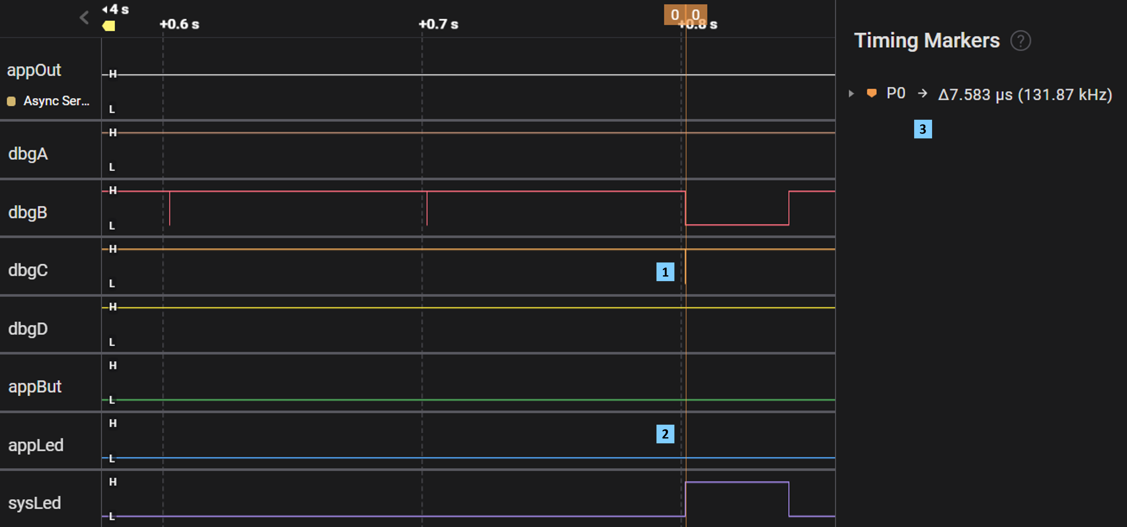
The %%[>cnt] statement outputs the (non-printable) 0x82 control byte followed by 2 bytes of payload.
The %%[>bits11] statement outputs the (non-printable) 0x81 control byte followed by 1 byte of payload.
The %%[c:bits11] statement causes the dbgC pin to rapidly toggle 2 times – since (bits11 == 0x1)
The ASCII character output of printf begins here – 0x63('c'), 0x6E('n'), and so on.
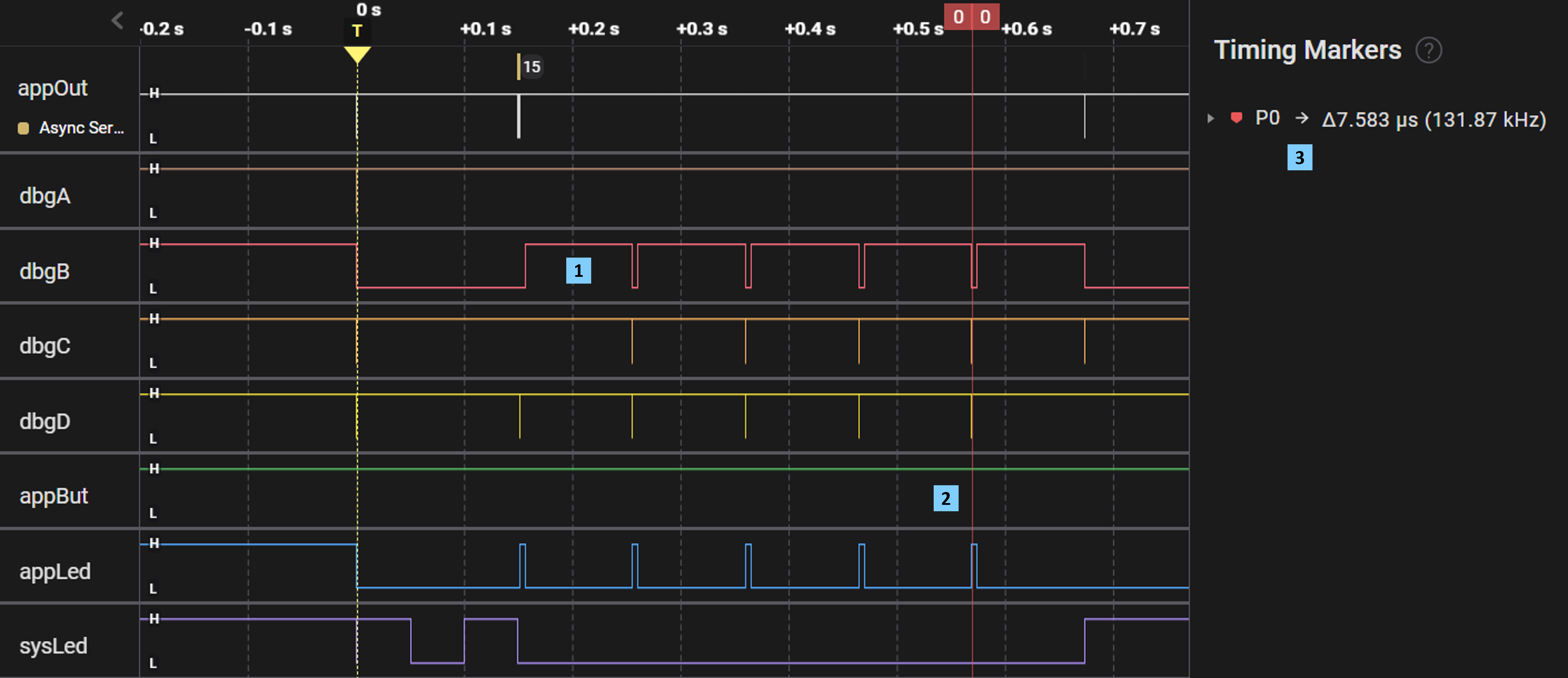
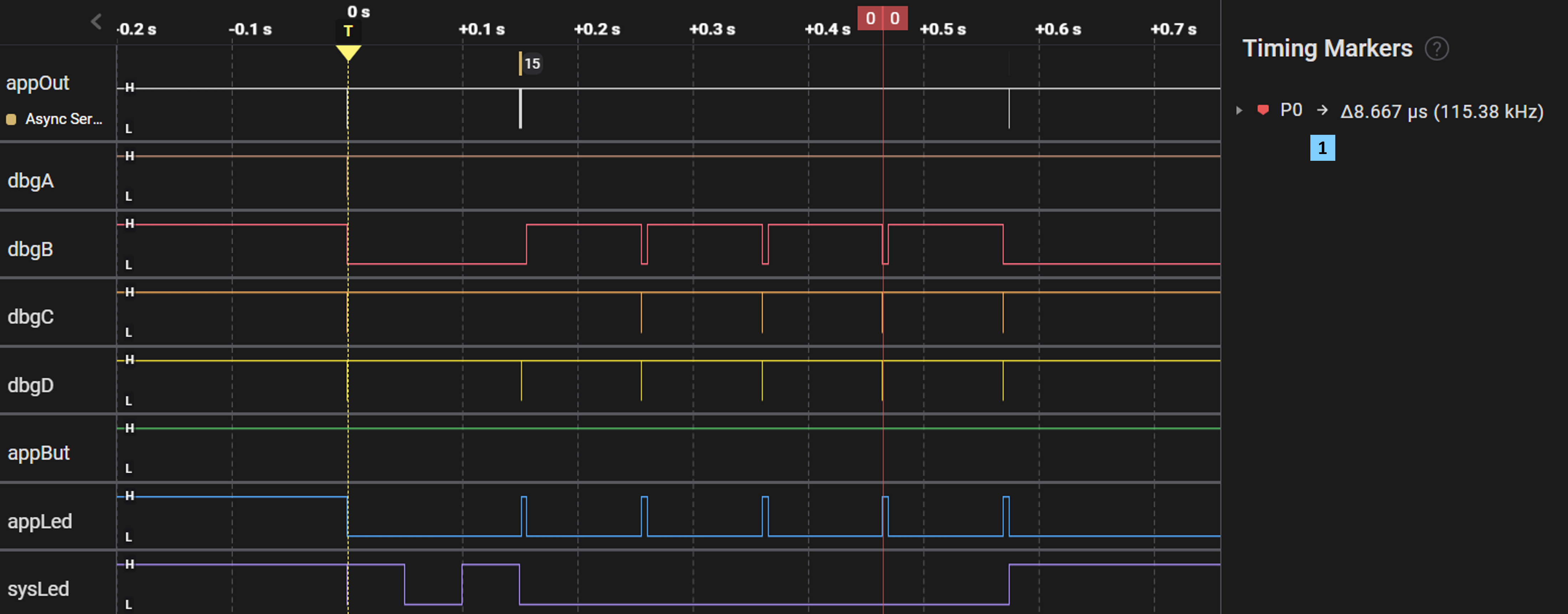
Tour 03 – threading with fibers
This tour centers around the FiberP program, which introduces a very lightweight threading construct termed a fiber. This tour also visits the EM runtime's (portable) implementation of fibers found in the FiberMgr module.

The %%[d] statement in blinkFB marks each point in time where the blinkF fiber begins execution.
The ~200 ms between blinkF cycles includes appLed on / off time plus FiberMgr dispatch overhead.
Tour 04 – button handlers
This tour centers around the Button1P program, which handles incoming events generated when pressing appBut on your board. This tour also visits the GpioEdgeDetectMinI interface that in turn extends the GpioI abstraction.
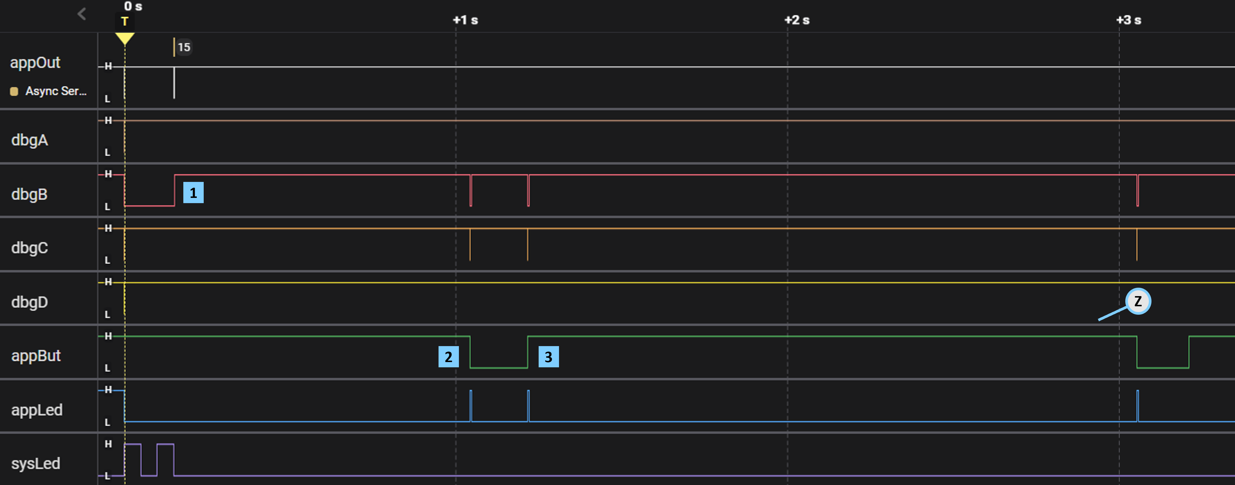
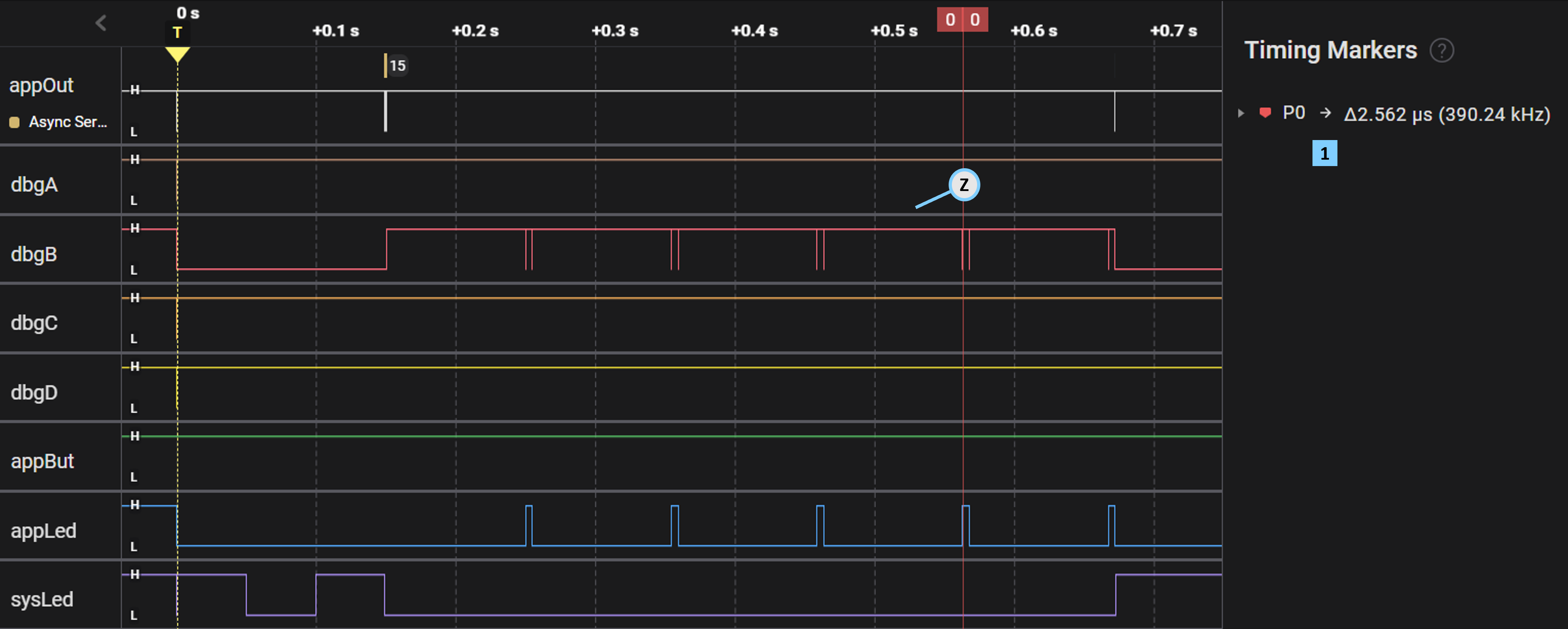
The EM runtime uses dbgB to mirror the MCU's execution mode [ L – actively running, H – awaiting wakeup ]
Pressing your board's button drives the appBut pin low; appLed then blinks shortly thereafter.
A 125 ns "glitch" on the appBut signal fired another event at this time – causing an extra appLed blink.
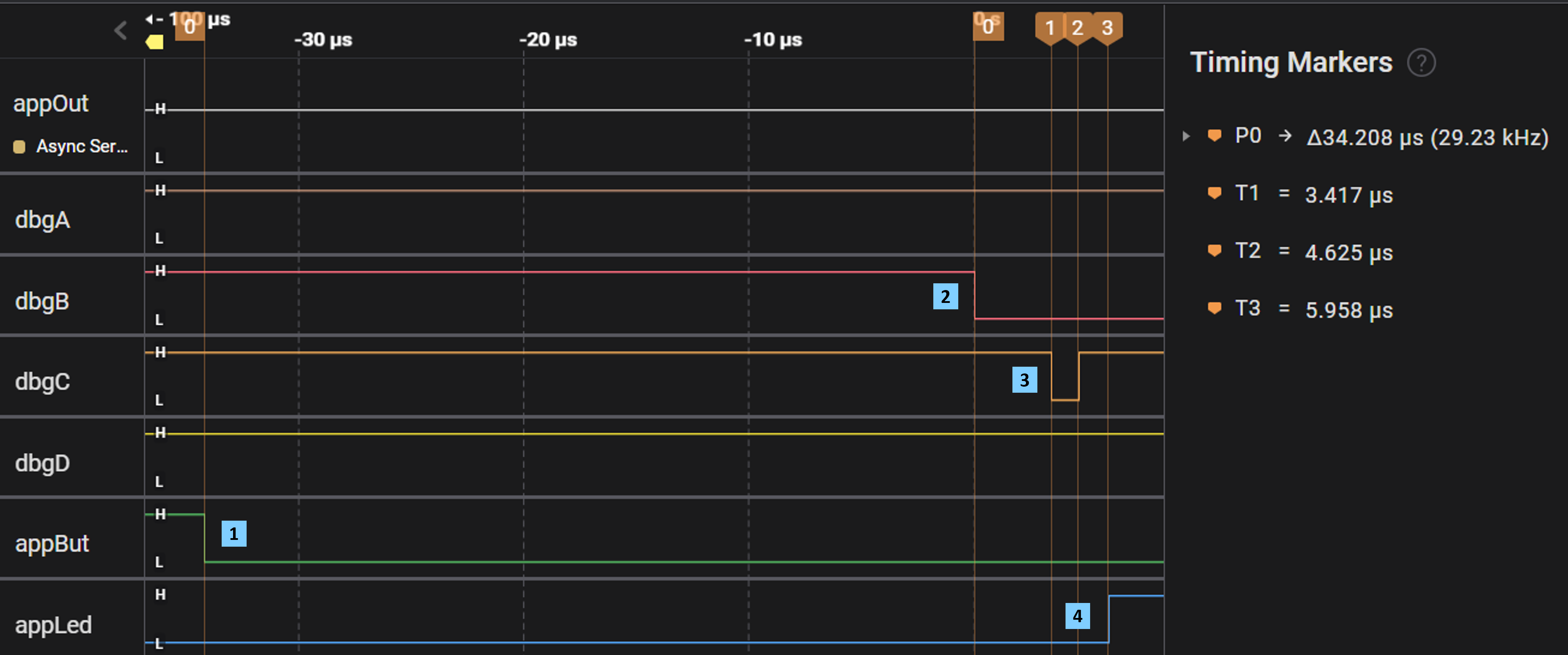
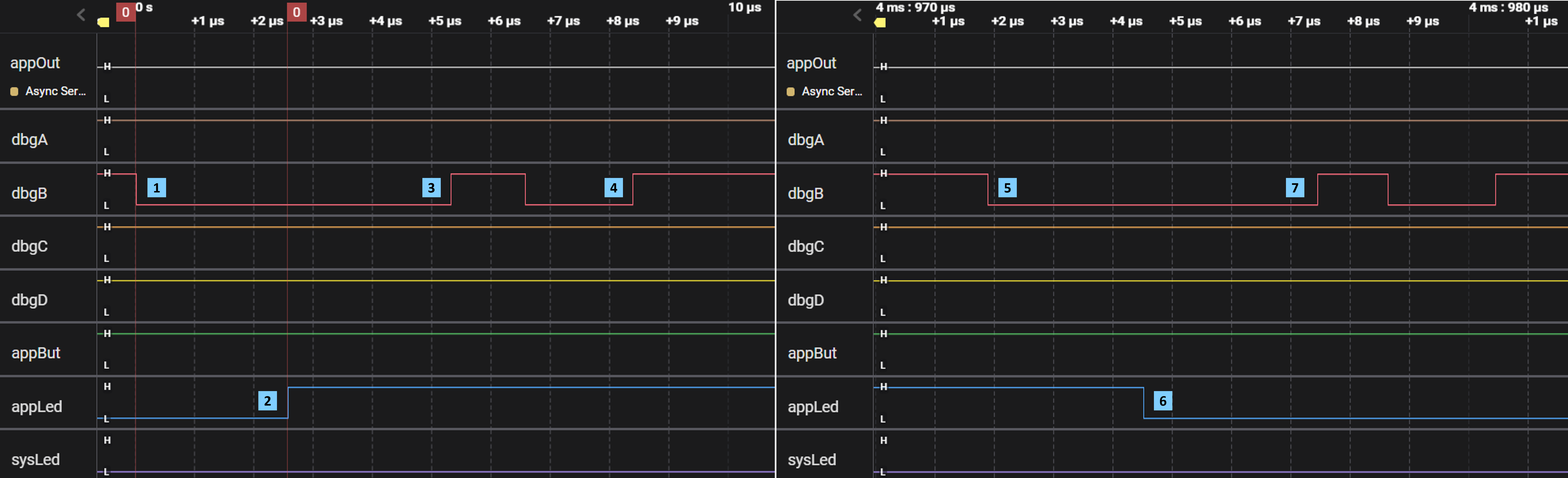
You've pressed appBut at this time, which then begins awakening the MCU from its low-power sleep.
Requiring 34.2 μs to fully power the MCU, dbgB's falling edge marks when Button1P starts actively running.
Control enters handler within 3.4 μs, whose initial %%[c] statement toggles dbgC for 1.2 μs
After some housekeeping, Button1P finally turns-on appLed – 5.9 μs since actively running.
Tour 05 – button fibers
This tour centers around the Button2P program, which uses a Fiber object to better handle incoming events. This tour also analyzes the performance impact of this approach compared with the earlier Button1P program.
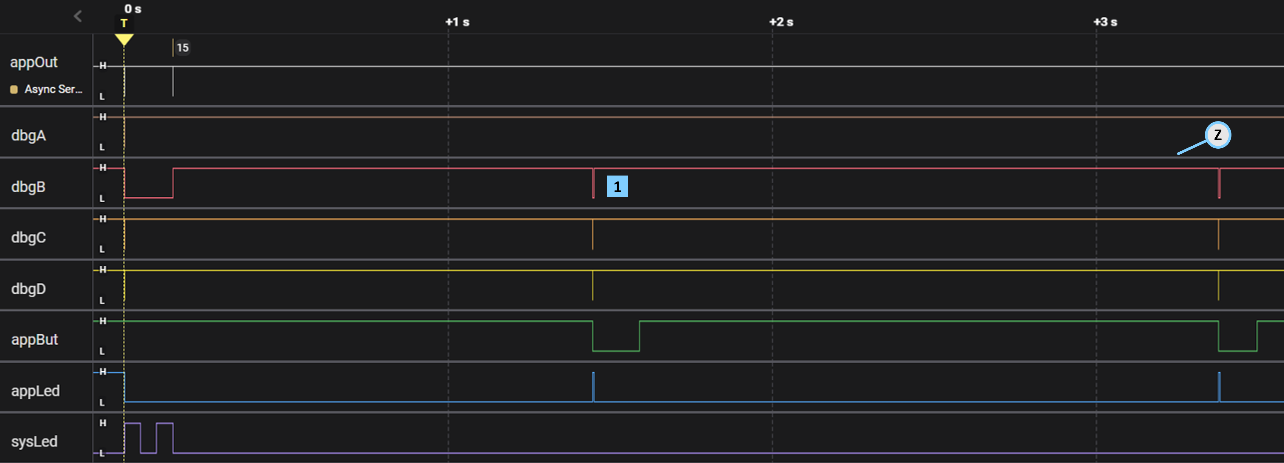
dbgB shows that Button2P awoke exactly twice in response to pressing appBut – no glitches this time !!!
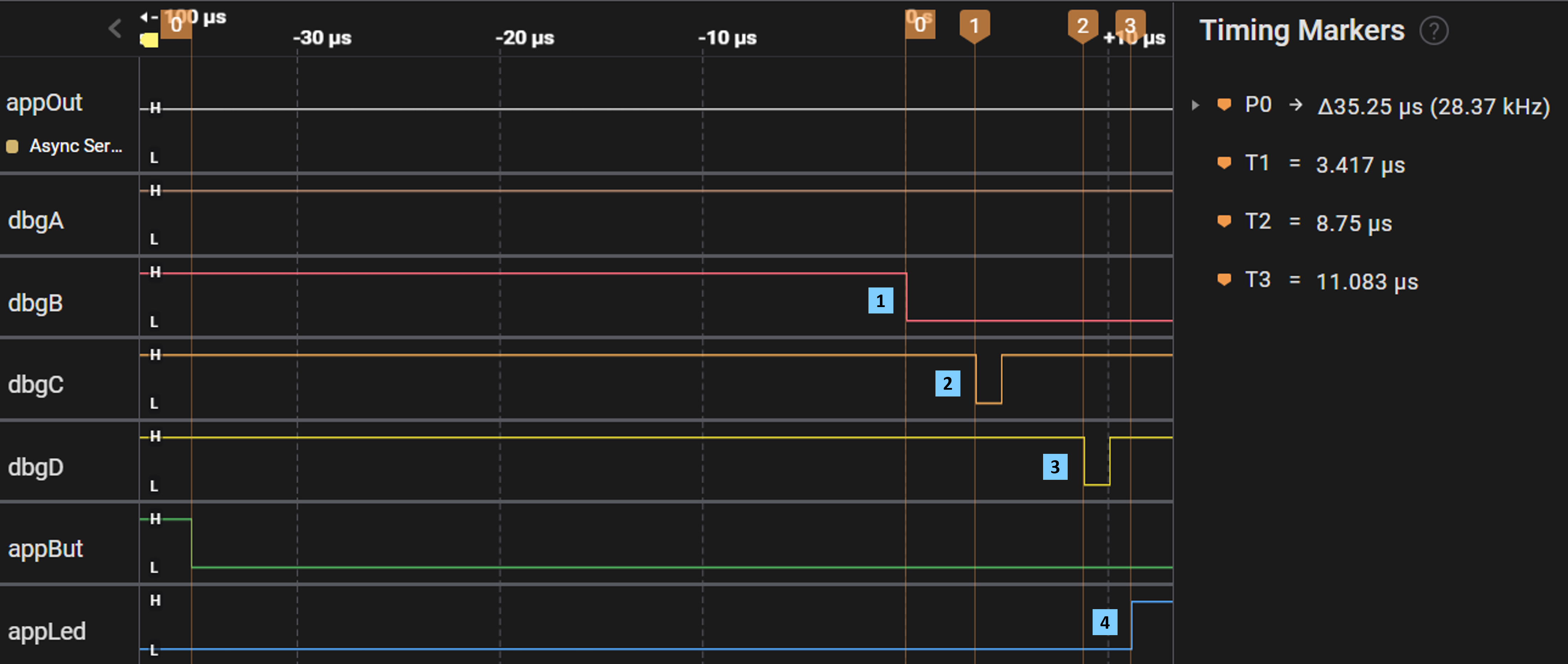
Button2P resumes execution in 35.2 μs; keep in mind that low-power MCU wakeup times can vary slightly.
Control then enters handler 3.4 μs later – consistent with the Button1P capture seen above.
Unlike Button1P, the Button2P handler readies the blinkF fiber which then gains control 5.3 μs later.
Finally, the blinkFB function turns-on appLed – with only ~5 μs of FiberMgr scheduling overhead.
Tour 06 – button objects
This tour centers around the Button3P program, which debounces button input signals in a portable fashion. This tour also visits the ButtonI interface along with a module implementing this interface – the latter generated by the ButtonT template at build-time.
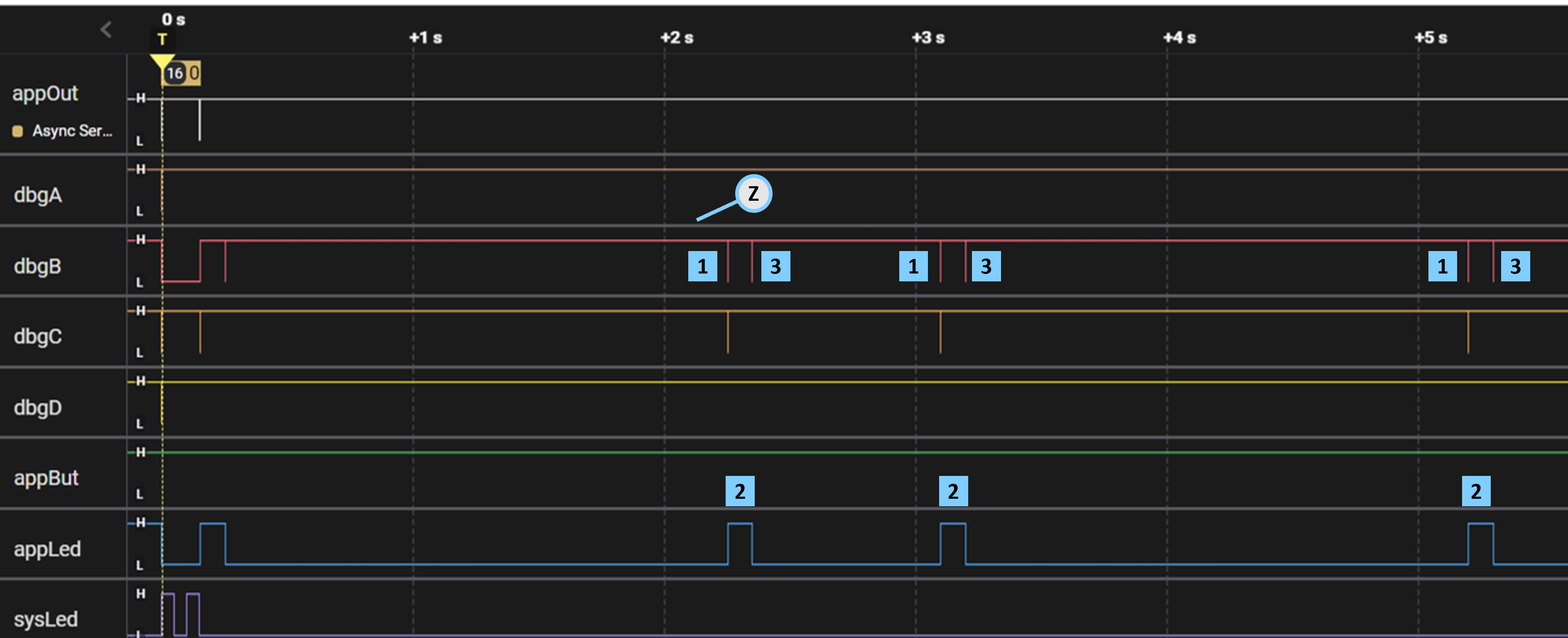
Once triggered by pressing your board's button, the EM runtime polls the state of appBut every 100 ms.
If pressed for ≥ 100 ms but ≤ 4 s, Button3P will blink appLed within 100 ms of releasing the button.
Hitting the 4 s mark, Button3P immediately blinks sysLed– regardless of how long appBut remains low.
After polling appBut for 4 s, the EM runtime invokes Button3P.onPressedCB which leaves a %%[c] mark.
Discovering that appBut remains pressed [ = L ], onPressedCB then blinks sysLed for 40 ms.
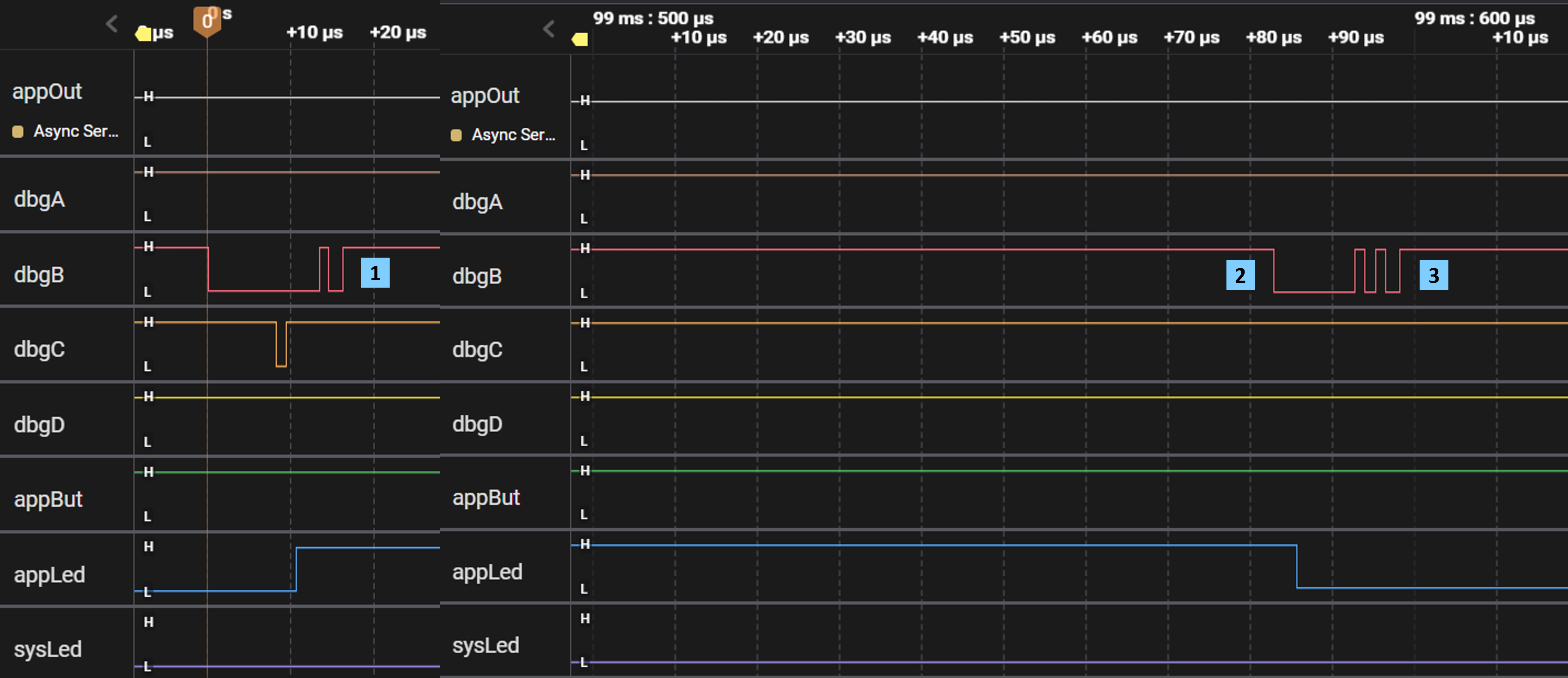
Only 7.5 μs elapses from dbgB falling to sysLed rising, which includes scheduling fibers plus 1.2 μs for %%[c].
Tour 07 – timer handlers
This tour centers around the OneShot1P program, which handles timer events that awaken the MCU. This tour also visits the OneShotMilliI interface, which abstracts the functionality of a short-term timer with millisecond resolution.
The dbgB signal shows that OneShot1P awakens from low-power sleep every 500 ms.
Once awake, OneShot1P toggles dbgC and dbgD before blinking appLed – like our earlier Button1P capture
The 7.5 μs "wakeup-to-blink" latency seen here includes the overhead of servicing an on-chip MCU timer.
Tour 08 – timer fibers
This tour centers around the OneShot2P program, which now uses Fiber objects to enhance robustness when handing timer events. This tour also invites performance comparision with the earlier OneShot1P program.
Fiber scheduling adds the extra 1.1 μs of latency seen here, compared with our previous OneShot1P capture.
Tour 09 – timer service
This tour centers around the PollerP program, which introduces a portable function for pausing execution at run-time. This tour also visits the top-level Poller module as well as the lower-level PollerAux module – both implementing the PollerI interface.
Without %%[c] and %%[d] marks, PollerP further reduces latency compared to OneShot1P and OneShot2P.
The [L] dbgB signal indicates that the PollerP program has awoken.
PollerP then calls AppLed.wink within 2.5 μs, which then asserts the appLed pin
Calling AppLed.wink 2.5 μs later asserts the appLed pin and then internally invokes Poller.pause.
Poller.pause proceeds to suspend program execution for 5 ms – the duration of the wink.
The EM runtime toggles dbgB once before awaiting the next wakeup [H] ; we'll explain more in a later tour.
An MCU timer event will eventually awaken the program 5 ms later, with dbgB now signalling [L] .
Control unwinds from Poller.pause back to AppLed.wink, which will now lower the appLed pin.
em$run finally regains control, and then suspends execution for 500 ms by calling Poller.pause directly.
Tour 10 – wakeup alarms
This tour centers around the Alarm1P program, which uses Alarm objects to schedule longer-term wakeups with (sub-)second resolution. This tour also visits the AlarmMgr module, which internally uses a proxy implementing the WakeupTimerI interface.
The Alarm1P program alternately awakens from a low-power deep-sleep of 2 s or else 750 ms in duration.
The program's blinkFB function winks appLed for 100 ms, with the MCU idling in the interim.
Once AppLed.wink returns, Alarm1P calls alarm.wakeup to re-enter an extended period of deep-sleep.
The single dbgB mark indicates the MCU has entered its "lite-sleep" mode, after Alarm1P calls AppLed.wink
The MCU awakens from its lite-sleep within 100 ms, returning to wink which then turns-off appLed.
The double dbgB mark indicates the MCU has entered its "deep-sleep" mode, after calling alarm.wakeup
Tour 11 – aligned wakeups
This tour centers around the Alarm2P program, which now aligns Alarm wakeups with a given time-window. This tour also re-visits the AlarmMgr implementation, seeing how it schedules the next wakeup event as well as the role played by the EpochTime module.

Note how the wakeups from deep-sleep align with a series of 1.5 s windows along the time-line.
Due to startup overhead, the first alarm.wakeup call deep-sleeps the MCU for only 1.250 s to stay aligned.
After a 5 ms appLed wink, this alarm.wakeup call deep-sleeps the MCU for 1.495 s to stay aligned.
But after a 100 ms wink, this alarm.wakeup call deep-sleeps the MCU for just 1.400 s to stay aligned.
Tour 12 – cyclic tickers
This tour centers around the TickerP program, which takes duty-cycled functions to a higher level. This tour also visits the TickerMgr module, whose implementation of Ticker objects emulates as well as builds upon the AlarmMgr and FiberMgr studied earlier.
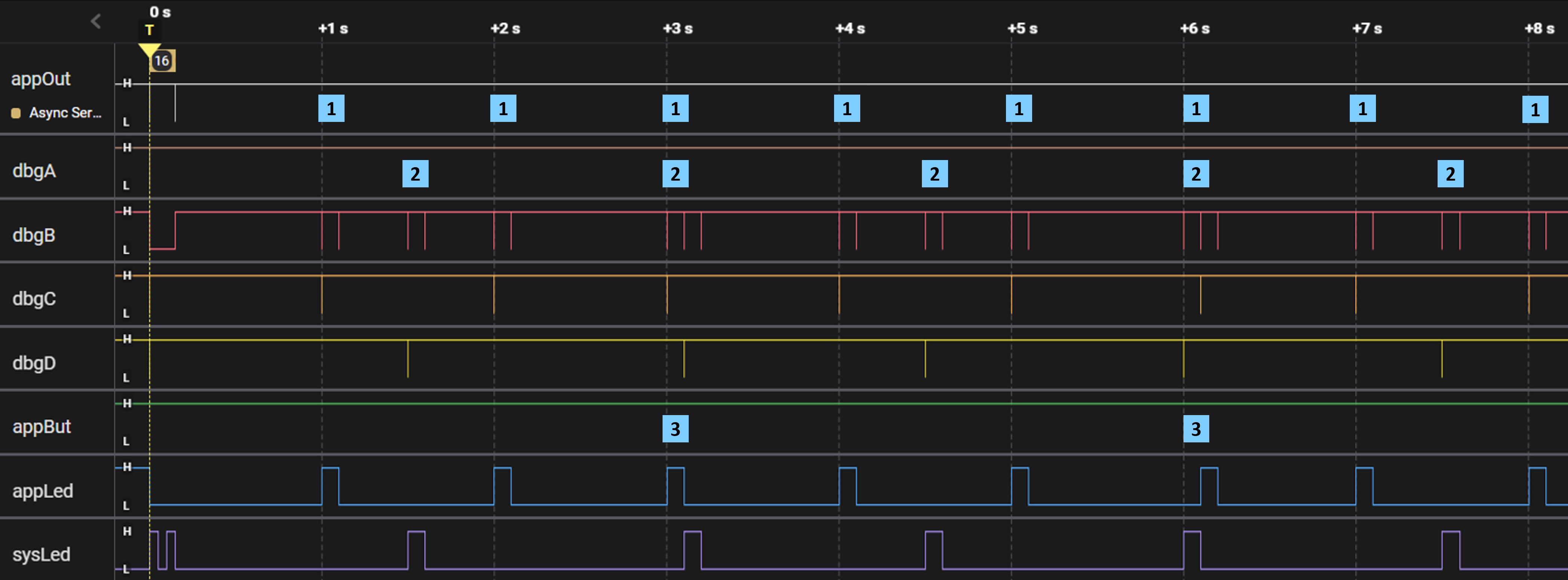
The appTicker.start call by the TickerP program initiates a train of 100 ms appLed winks, spaced 1 s apart.
The sysTicker.start call by TickerP then initiates a train of 100 ms sydLed winks, but spaced 1.5 s apart.
When appTicker and sysTicker wakeups coincide, their callbacks run on a first-come, first-served basis.