Optimizing power over time
We put forth a rather bold proposition in Using EM: If you can't see the problem, you can't fix it !!! As we toured the EM runtime, logic captures for each example program gave you an important perspective – that of program state over the course of time. Informally termed "real-time debug", this kind of logic trace proves invaluable to both quantify program execution time at sub-μs resolution, as well as to verify proper sequencing of program execution.
This article expands this proposition into the domain of energy consumption – by now tracing MCU power over the course of time. With many resource-constrained MCUs targeting always-on applications that run using batteries and / or harvested energy, power profiles captured by a precision energy analyzer nicely complement the "real-time debug" traces captured by a logic-state analyzer.
Until recently, the cost of a high-quality energy analyzer would often exceed $10,000 – far beyond most of our budgets. The recent arrival of the Joulescope JS220 precision analyzer does, however, afford order-of-magnitude relief on pricing. And the STM32 Power Shield offers an even more affordable option at < $100.
Help wanted – someone familiar with the STM32 Power Shield
For now, though, we'll stick with the Joulescope JS220 as our energy analyzer. And even if you don't own a JS220, we recommend downloading the (free) Joulescope UI software as well as the original power capture files presented throughout this article.
Mcu power modes
The Tour 10 – Logic Capture seen here in Using EM introduced the terms "lite-sleep" and "deep-sleep" corresponding to distinct marks on dbgB. Recalling the Alarm1P example, this program enters the MCU's deep-sleep mode %%[b:2] after calling alarm.wakeup. But after calling AppLed.wink – which internally pauses execution for a much shorter period of time – the program instead enters the MCU's lite-sleep mode %%[b:1].
While each vendor often has their own jargon for these power modes (IDLE, PAUSE, SLEEP, STOP, SUSPEND, … ), we'll uniformally use the following terminology when measuring power across different MCUs supported by EM:
ACTIVE |
CPU core running – MCU peripherals powered on when needed by CPU |
PAUSE |
CPU core idling – MCU peripherals powered on when needed for CPU wakeup |
SLEEP |
CPU + most peripherals powered off – wakeup via special "always-on" peripherals |
HIBERNATE |
entire MCU powered off – CPU "reset" interrupt triggered by external HW devices only |
As application software transitions amongst these modes, the power required to operate the MCU can range from milliwatts [ACTIVE] to microwatts [SLEEP] – and even down to nanowatts [HIBERNATE] if the application wishes to suspend execution indefintely.
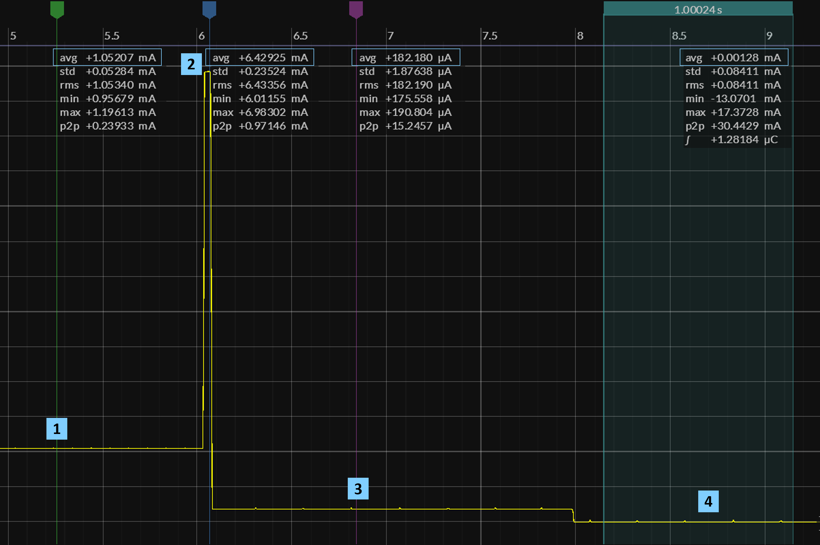
To quantify these MCU power modes on your target board, we'll use the Button3P program highlighted in Tour 06 to obtain these readings. The Button3P Power Capture image below marks four distinct points during program execution, where we'll use the JS220 to measure the amperage instanteneously drawn by the MCU.
We've pressed appBut for almost 4 s, with the program testing appBut every 100 ms. [PAUSE]
Crossing the 4 s threshold, the program now blinks sysLed for 40 ms using a busy-wait loop. [ACTIVE]
The program sleeps until the next button event, even though appBut itself remains pressed. [SLEEP]
With the button now released, the program remains asleep while drawing even less current. [SLEEP]
TBD – open for suggestions
TBD – open for suggestions
Because the JS200 samples at a relatively slow 1 MHz rate (compared with the CPU clock), the capture around marker shows a series of ripples spaced 100 ms apart which in fact correspond to very brief CPU wakeups from PAUSE to sample appBut; a similar train of blips occurs around markers and , which here represent an internal duty-cycled recharge of the MCU's DC/DC converter or LDO regulator.
By in large, these current measurements align with specifications found in the MCU vendor's datasheet. Do note, however, that the ACTIVE reading recorded at marker includes current drawn by the board's LED as well as the CPU itself.
Measuring energy
While important, MCU power specifications such as [SLEEP = 1.5 μA] or even more generalized forms such as [ACTIVE = 53 μA / MHz] say absolutely nothing about the overall energy efficiency of an ultra-low-power embedded system built around this particular MCU. To gain this perspective, we must simultaneously consider the software running on the MCU and answer critical questions such as:
Once awakened, how quickly can our application software go back to sleep ?!?!
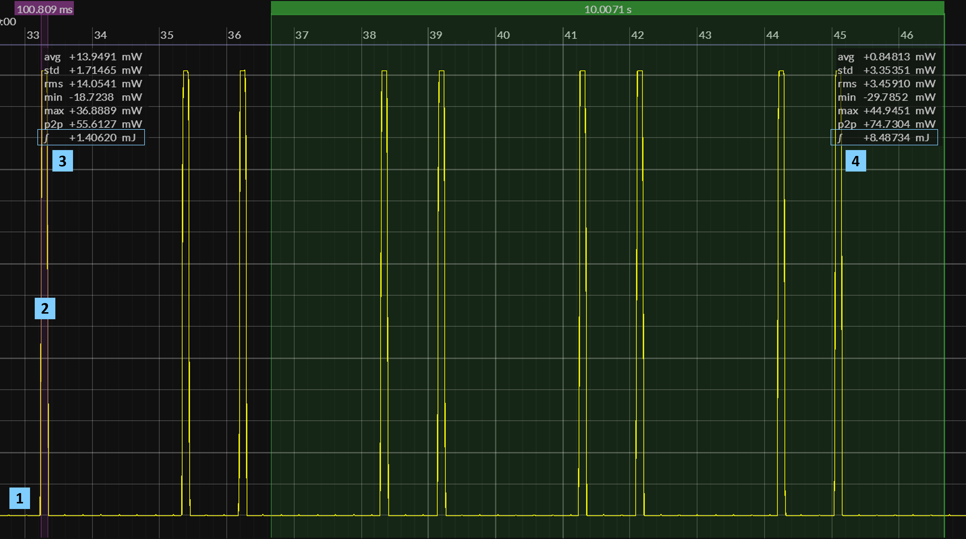
By knowing the amount of time a program spends in the various MCU power modes, we can begin to quantify the overall energy efficiency of an embedded system. To illustrate the methodology we'll apply to measure energy consumption, consider the following JS220 capture of the Alarm1P example, which complements the logic capture found here:
EM Setup: ti.cc23xx/segger_default
TBD – open for suggestions
TBD – open for suggestions
Alarm1P spends the majority of its time in SLEEP, typical of many embedded applications.
Once ACTIVE, the program calls AppLed.wink and then enters PAUSE mode for 100 ms;
awoken from PAUSE, the program calls alarm.wakeup and moves from ACTIVE to SLEEP mode.
The energy (in millijoules) consumed during this 100+ ms SLEEP - ACTIVE - PAUSE - ACTIVE - SLEEP interval.
The energy (in millijoules) consumed over an arbitrary 10 s interval encompassing six wakeups from SLEEP.
While time intervals and differ by a factor of 100, the total energy [ mJ ] consumed over these intervals differ by only a factor of ≈ 6. Needless to say, decreasing the number of wakeups over a given timeframe will always improve overall energy efficiency. Often, though, application requirements will dictate the frequency of these wakeup intervals – as high as once per second in many embedded systems.
Less code, less energy
Introducing EM hypothesized that reducing code size could have a potentially dramatic impact on the size, power, and cost of future MCU silicon. Focusing on the dimension of power for now – and targeting legacy MCUs – we can already quantify the relationship between "less code" and "less energy".
Needless to say, minimizing the number of CPU instructions executed while ACTIVE will only reduce overall energy consumption – assuming our software still meets a given set of application requirements. With its uncanny ability to reduce code size, the EM language and runtime should benchmark quite favorably against more conventional C/C++ RTOS platforms such as Zephyr.
Help wanted – embedded programmer familiar with Zephyr
Setting aside the larger "EM vs C/C++" discussion for now, we'll focus instead on a very effective technique for reducing energy consumption using the same Alarm1P program executing on the same target MCU board. Quite simply, the EM runtime will automatically copy the .text and .const program sections into fast, on-chip SRAM at startup – rather than leaving this readonly code + data in Flash memory, where they conventionally reside.
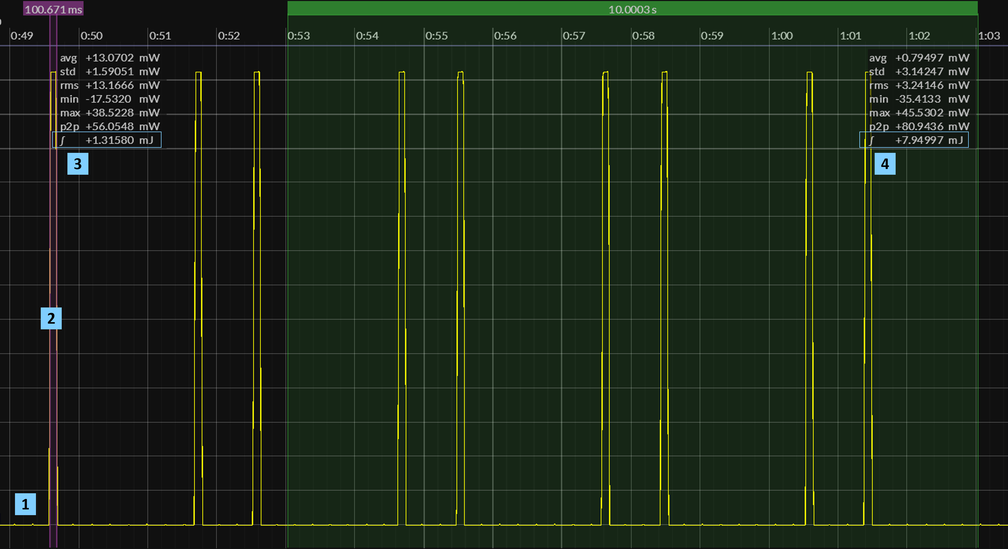
To quantify the impact of this change, compare the following Alarm1P Power Capture with our earlier baseline – paying close attention to the total energy [ mJ ] consumed at intervals and in each capture.
EM Setup: ti.cc23xx/segger_sram
TBD – open for suggestions
TBD – open for suggestions
While we do see a modest 10% gain in energy efficiency here, don't forget that the Alarm1P program actually fetches very few instructions – with the MCU remaining in a (lower-power) PAUSE mode for most of interval . Imagine, though, a duty-cycled "sleepy" application that executes a non-trivial mix of math functions and control code when ACTIVE: significant improvements during interval would also lower overall energy consumption reported at .
With modern MCUs clocked at ≈ 50 - 150 MHz , these architectures invariably employ a HW cache to mitigate wait-states which would otherwise stall the CPU when fetching instructions or constants directly from slower flash memory. But SRAM has no such limitations, as this class of memory can easily sustain read rates in excess of 500 MHz . The CPU hence runs at maximum efficiency, allowing the application to re-enter SLEEP that much sooner.
Assuming the program image can actually fit within SRAM – a far more scarce resource than flash – the EM distro for your target MCU board can actually disable the flash memory and its HW cache during em$startup to further reduce ambient power. Paradoxically, running the CPU at its highest possible clock rate will often decrease overall energy consumption when executing – again, by minimizing the amount of time spent in the ACTIVE mode.
In the future, we'll have additional articles under Mastering EM that benchmark more sophisticated EM applications that nevertheless can execute entirely from on-chip SRAM. In the meanwhile, ponder the following question:
Knowing EM applications need only a small SRAM to run, how might we architect future MCUs ???